Every month I get our electric bill emailed to me and each and every month, I wonder what generated all those KiloWatts we used, let alone all the $$$ to pay for them. Granted the HVAC system is probably going to take the #1 position as the “BIGGEST ENERGY HOG” in our house, being as we live in Florida, but wait, what about the Clothes dryer? The Hot Water Heater (WOW)? Those things can really add the watts used, fast. Then there is the coffee pot 5x a day. What about those “Parasitic” loads on the system, that are on 24/7, like the cable TV box, the TV, alarm clocks, internet router, laptop charging, microwave…. and the list goes on. Is there a PEAK and Non-Peak time for calculating the usage cost? How can I use this information to lower my monthly electric bill?
I have a Kill-A-Watt AC usage monitor that I used in the past, but that got to be a big pain in the butt to constantly go from unit to unit to monitor the watts used. Then write the numbers down and lose them. Unfortunately, it only gave me a “Point in Time” number and not useable in calculating its total usage over 30 days. I designed a few Arduino energy monitors using CT’s (Current Transformers) to monitor the electrical usage, but the programming got to be a little to much, especially when adding more things to monitor and calculating usage. I can program, but I am only so good at it.
I finally decided it was time to invest in an Energy Monitor that will do EVERYTHING for me. I researched and researched and finally decided on a GreenEye Monitor (GEM) made by BrulTech. At first I was skeptical about purchasing a system that monitors you home’s energy as most of the research showed that you needed to store the data online with the mfr, and some even wanted a monthly subscription fee to store and display my data. In the past I have had many of those manufacture’s go south, lost all my data and decided that I needed a system that would allow me to keep all the data local in my own dB, on my home network and display the data in a local webpage. I am not to demanding, am I? I also wanted the option to access the data for personalized reports, import it into my other systems (Home Automation… another project to post) and up-load the data to some of those Internet monitoring sites where you can share the data with others.
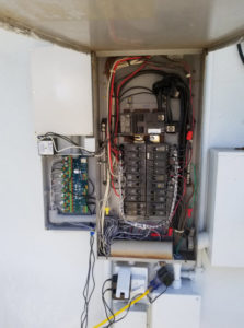
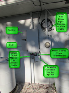
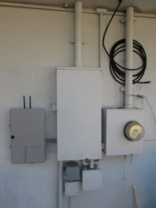
The unit has arrived and “Let the FUN begin”! I have been reading the users manual in advance of receiving the unit (even before I decided to purchase it), so I have an idea as to what I needed to do in order to complete the project. Since my unit will be mounted outside on the side of the house, I needed to purchase a 2 weather proof PVC boxes to mount on the wall next to the Main Electrical Service panel. I was lucky and they arrived before the GEM, so I installed them.
Oh, one additional issue for this project. I will be adding about 10Kw of SOLAR between now and next summer, so I may have to move theses boxes for the SOLAR electrical parts. I decided to leave the Current Transformers (CT’s) with their original long cable lengths, just in case. The problem is how to store 30 inches of cable times 18CT’s. I decided on using a 2″ electrical PVC pipe to put the slack into. I also did not want to have the CT wires just dangling in the electrical box so I had some waxed twine and laced the cables down to the PVC pipe. Yes, I could have used cable ties, but I left my supply in our RV up in the North GA mountains. It looks better than the wire just laying there looking like a big ball of spaghetti.
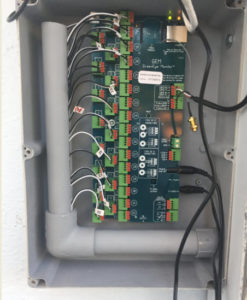
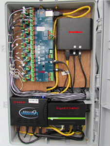
I wanted to make sure the CT cables in the box, where the GEM was installed looked neat, so I put electrical PVC conduit in to the PVC box. This was a real pain as the CT wires were getting all twisted together. I added a vertical pipe with a slot cut in it so that the CT wires could be fed through the pipe and be able to pull them out one by one to connect to the GEM connectors. Actually does look pretty nice, if I must say so myself. It only took me 3 attempts (along with rain delays) to get it to look this way and know which CT’s went to which connectors in the GEM. I still need to mark each CT cable with the electrical box circuit breaker number.
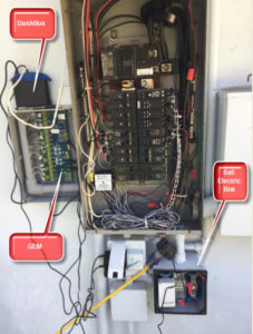
So now that I have the GEM mounted, the CT’s wired in and looking half way decent, I need to wire in the DashBox. What is a DashBox you ask? The GEM collects information from all the sensor inputs and sends that data to the DashBox. The DashBox then takes that information and stores it in its own database (part of the unit), and has a LOCAL webpage for the user to access and display the data in real time. Wait, the DashBox needs to connect to my local network which happens to be 50′ away in my home office. Well, since I read the user manual a few times, I was prepared and already ran a CAT5 cable between the weather proof PVC box that houses the DashBox and my home office. OK!!!! It also has a Wi-Fi option I could have used, if I did not want to run the CAT5 cable. Maybe one day I will activate that option. I had 2 options as to where I could mount the DashBox, (1) outside where it is next to the GEM or (2) inside next to my Wi-Fi router. I chose to mount the DashBox outside next to the GEM, so that when I add my battery backup out side, both units will keep running without AC power. Had I installed the DashBox in my office, it would have had power for about 30 minutes from the UPS while it shut down my computers. Outside if should stay running as it will have a small SOLAR panel to keep the battery charged. Also, when I start using the dB to run reports, it will be much easier to determine power outages as the line voltage will have “0” volts in the records, whereas if I did not have the battery backup, there would be no records for that timeframe, and I would have to create a query to look for missing records… which would open another can of worms.
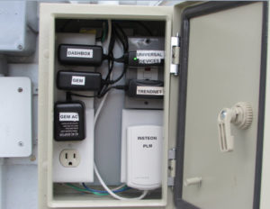
Opps, wait a minute. The GEM needs a transformer to power it and has an AC transformer to monitor the LINE voltages. The DashBox also has a transformer to power it. OK, now what. I am mounting this equipment on the back of the house. I have a PVC electrical box that was used for my old X10 Home Automation system (to control the outside lights) that I am replacing (another project), I rewired that to use with the new system. After a few more cloud bursts, I managed to get the outlets wired into a 6×6 electrical box. Nothing like having fun wiring in the system and having to take time out to sit in the living room, sipping on a cup of coffee, complaining. Well, not really complaining, I have 10 rain barrels that needed to be topped off for the garden sprinkler system (400+ gallons). That will be another project… wiring up moisture sensors, rain barrel water level sensors, the rain gauge, and weather forecast to water or not to water the garden. That is an Arduino project that is in progress as we speak.
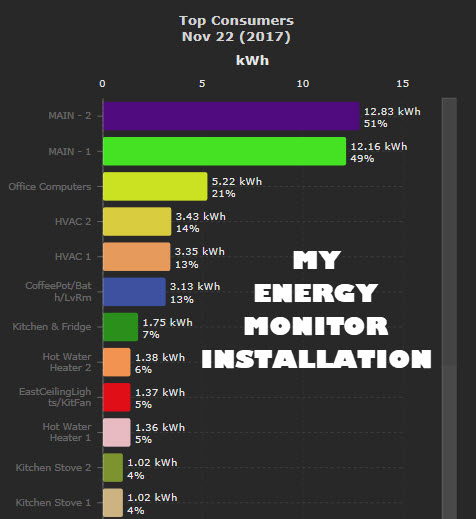
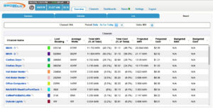
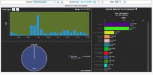
Now that the install has been completed (well almost completed) it is time to see if this system really meets my expectations. I plugged in the power transformers and the system lights came to life flashing on and off, which is a good thing. After a few minutes the system seemed to be up and running, based on the lights. I went into the office and activated the DashBox’s webpage interface on my laptop. I was impressed the webpage was already showing the outputs of the CT’s, the AC line voltage and my single temperature sensor which keeps tract of the temperature in the DashBox’s compartment. I had a few network setup items to complete and the system was up and running. WOW!!! This is so COOL!!!! I was going around and turning on the clothes dryer, watching the water heater elements add a lot of watts to the daily total. All those previous attempts of monitoring my energy consumption here at home, well there is no comparison. The BrulTech GEM/DashBox was as easy to install as the reviews I read said it was.
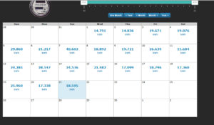
As I was watching the loads on the system (look at Nov 7th, in the above picture), I noticed that the HVAC, Clothes Dryer, and Water Heater watts being used were way out of range. I went back to the documentation and noticed that these high Amp CT’s were to be plugged in to different connection points in the GEM. Walked outside, moved the 6 wires to the proper connections and the usage was then correct…. I somehow overlooked this section in the pre-read of the documentation.
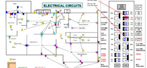
It has been a few weeks since the install has been completed and I have NO complaints regarding this system. It was a “No Brainer” for the install, the documentation answered 99% of my questions and the remaining questions were answered by searching their GREAT user forum, where those guys really know their stuff. I am still learning the software features and already have plans for some sensors of my own to be added to the system. I have already rewired a few of the house’s electric circuits in the attic as I am still trying to figure out the logic used when they were installed back in 1957 when the house was built, or maybe when it was converted to 100Amp 220 service in the 80’s. When we purchased this house in 1998, I decided to make a wiring diagram of all the house’s electrical outlets, lights, HVAC…. and show the circuit breakers they were assigned to. I have a copy of the wiring diagram taped to the inside of the Service Panel. That has been a real blessing when I need to trouble shoot electrical problems or add circuits to the existing ones. Everyone should take the time and create one of these electrical layouts.
So, if I were to do this project all over again would I do it differently? Yes and no! The only change I would have made was when I got the equipment, I would have laid it out on my work-bench and set it up and tested it there. I was lucky that there was no need to un-mount the equipment and troubleshoot any issues. Other than that I would do everything the same. As I add more things to the system I will update this blog. Let me know what you think. This is my first attempt at publishing a project, unfortunately some of my pictures and videos disappeared when I switched smart phones, well I thought I backed everything up.
Finally, I want to take a moment to thank the BrulTech staff for their GREAT service. It is a pleasure working with them, the SALES person (she knows who she is:-) is FANTASTIC!!!! Thank you BrulTech. If you decide to purchase one of their systems, tell them Don sent you!
————————————————————————————————————————-
Here is the ALMOST finished outside project. The last thing I need to do is re-run the transformer cables through the electrical boxes. I probably should have used a 1″ PVC pipe between the Service Panel and the GEM box as the power cables have a large plug on them and the pipe has all the CT wires running through it.
02/28/2018 – UPDATE
After a successful installation, and as time passes, what seemed to be the best setup for the project, eventually become a “Pain in the Butt”! When I installed the 2-water proof weather resistant boxes with the GEM and DashBox in it, it seemed to be the right combination, but after time the 12 screws that hold the covers in place became a “PAIN” each time I wanted to do some work in the boxes.
I started searching for the “ULTIMATE” box. Well, after a few days of looking I came across the latest selection for the weather resistant home for the GEM/DashBox. it is an oversized “CABLE” company type box. It is weatherproof and can be secured. So, I ordered one.
I shut down the system and pulled all the CT cables off the GEM. Took down the old boxes and installed the new CABLE box. I made a back board to mount the GEM/DashBox on, which seems to be working GREAT. I reinstalled the GEM (minus the Wi-Fi Module) and the DashBox along with an “UNMANAGED” 5-Port Gigabit Switch”. I chose this method so that I did not have to run a new CAT5 cable to the Home Office, located 50′ away, at the other end of the house.
I then connected the existing Cat5 cable (HomeNetwork/Internet connection) to the Gigabit Switch along with the GEM and DashBox. So far, this set up is working great. I disconnected the Cat5 to the HomeNetwork and the GEM continued talking to the DashBox, without the HomeNetwork/Internet connection. I know the two are connected by the STS cable, just thought of that. I am thinking of going from the STS cable to having the GEM communicate to the DashBox via the Ethernet cable, not sure if this will be a good or not so good idea. This “UPGRADE” will be a big benefit for my next project, which is SOLAR/Battery powering GEM/DashBox/ISY994iZ/Network Switch. The units will continue to work 24/7 with or without the “Grid” power, which will make my database queries easier. The records will show “0” volts/data but there will still be a record. This way I do not have to look for sections in the data that have gaps with no records, the records will be there with no data in them. Sooooo much easier for me. Although, I am not sure as to how the BrulTech programs will handle the records with no data, should not be an issue.
I installed the ISY994i controller in the lower left section of the box (reason for the Gigabit Switch). This will keep everything in one location and have a continuous power source (even though no ISY commands can be carried out because of no 110VAC power). Since my house was built in 1957 (I am 3rd owner), it has plaster walls which have a metal mesh that the plaster adheres to. The problem is that the mesh is contacting all the electrical outlet boxes and makes for an GREAT signal blocker. With the units all in the same location, I no longer have to worry about the Xbee in the GEM talking to the Xbee in the ISY994iZ. Now that the ISY994iZ is in the panel, it works fine with the GEM.
I think that this should be the final home for the GEM/DashBox/ISY994i and maybe the ISY994i. Time will tell!
03/01/2018 – UPDATE!!!!
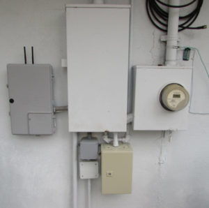
Yes, there is another upgrade… see the 3 smaller electrical boxes under the main service box? They contain the needed power transformers for the GEM, DashBox, ISY994iZ and the Network Switch. Well, I decided to purchase a metal box that will be large enough to house all 5 of the needed transformers.
05/21/2018 – UPDATE!!!!
I guess I got behind a little with my update. In March I mentioned that I was going to purchase a metal box to house all of the power transformers needed for the Home Automation and Energy Monitor electronics. Well I ordered the Metal Box and installed it with all the power transformers inside. It makes things a lot neater having them all in one location, not to mention that I no longer had to guess which electrical box the transformer was in.
I decided to install a GFCI outlet and have the other outlets tapped to its load terminal. Just a “Safety First” decision, since it is outside. I measured out where I wanted the outlets to be mounted and set them up on my workbench and wired them in. I then moved the wired outlets into the Metal Box and mounted them. It was a little bit of a challenge as there was not that much room for my long fingers, but I managed to get it completed. I wired the circuits to the main service panel, tested each outlet with a multimeter, plugged in the transformers and flipped the panel breaker. All the equipment started up and is working fine. I still need to paint the newly installed cases just to keep the wife happy.
NEXT, onto PHASE II, running all the 5VDC power from a SOLAR powered battery system (and only switch to 110VAC power should the battery power stop working.. Alerted by text of course). I have all the parts, just need the time. I am still tossing around the 2 options… (1) Running the systems off of battery/SOLAR and switching to AC should the battery power drop below the 5 VDC level or (2) running the systems off of a single 5 VDC transformer and switch to battery/SOLAR in the event of a 110VAC power failure. Still leaning toward option #1
Thanks for reading:-)
Some of the projects that I am working on that will appear on this site are:
- Converting my Home Office to SOLAR power (with battery backup for when the sun goes down), this will fit in nice as I add the 10Kwatts of SOLAR. This project will probably have to add the media center to the SOLAR/backup and will not be connected to the GRID.
- Home Automation.. Garden Sprinklers/Rain barrels/sensors using Arduino and Universal Devices ISY994i system.
- Enhancing my security video system to allow for individual camera reboots (all 16) from anywhere on the internet. Some of the older cameras have a mind of their own.
- Automated RV bed lifting system to access storage beneath the bed.
- RV system monitoring (while not in use), motion sensors, door/window sensors, battery weight (water level monitoring), SOLAR/battery status…. using cell service to transmit data to my website.
- Refrigerator alarm system… one of the doors sometimes does not close all the way when pushed, but looks like it is, along with temperature, humidity and fridge that is not cooling properly.
- Wireless water flow meters at the main city meter, hot water tank, cold water, yard, clothes washer.
- Wireless toilet flush sensor that sends a pulse (times the gallon and a half per flush) to monitor water flow.
- There are many more to follow.
- —— 11/24/2017, 09:56AM——
